- Posted By: freeproject
- Comments: 0
- Posted By: freeproject
- Comments: 0
Electricity Bill Payment System Activity Diagram
This is the Activity UML diagram of Electricity Bill Payment System which shows the flows between the activity of Consuptions, Customers, Readings, Bills, Units. The main activity involved in this UML Activity Diagram of Electricity Bill Payment System are as follows:
- Consuptions Activity
- Customers Activity
- Readings Activity
- Bills Activity
- Units Activity
Features of the Activity UML diagram of Electricity Bill Payment System
- Admin User can search Consuptions, view description of a selected Consuptions, add Consuptions, update Consuptions and delete Consuptions.
- Its shows the activity flow of editing, adding and updating of Customers
- User will be able to search and generate report of Readings, Bills, Units
- All objects such as ( Consuptions, Customers, Units) are interlinked
- Its shows the full description and flow of Consuptions, Bills, Units, Readings, Customers

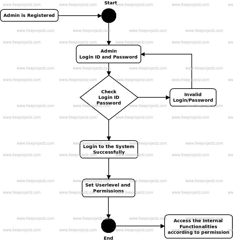
Login Activity Diagram of Electricity Bill Payment System:
This is the Login Activity Diagram of Electricity Bill Payment System, which shows the flows of Login Activity, where admin will be able to login using their username and password. After login user can manage all the operations on Readings, Consuptions, Customers, Units, Bills. All the pages such as Customers, Units, Bills are secure and user can access these page after login. The diagram below helps demonstrate how the login page works in a Electricity Bill Payment System. The various objects in the Units, Readings, Consuptions, Customers, and Bills page—interact over the course of the Activity, and user will not be able to access this page without verifying their identity.
- Posted By: freeproject
- Comments: 0
Electricity Bill Payment System Class Diagram
Electricity Bill Payment System Class Diagram describes the structure of a Electricity Bill Payment System classes, their attributes, operations (or methods), and the relationships among objects. The main classes of the Electricity Bill Payment System are Bills, Customers, Connections, Units, Readings, Consuptions.
Classes of Electricity Bill Payment System Class Diagram:
- Bills Class : Manage all the operations of Bills
- Customers Class : Manage all the operations of Customers
- Connections Class : Manage all the operations of Connections
- Units Class : Manage all the operations of Units
- Readings Class : Manage all the operations of Readings
- Consuptions Class : Manage all the operations of Consuptions
Classes and their attributes of Electricity Bill Payment System Class Diagram:
- Bills Attributes : bill_id, bill_customer_id, bill_number, bill_type, bill_receipt, bill_description
- Customers Attributes : customer_id, customer_name, customer_mobile, customer_email, customer_username, customer_password, customer_address
- Connections Attributes : connection_id, connection_name, connection_type, connection_description
- Units Attributes : unit_id, unit_name, unit_type, unit_description
- Readings Attributes : reading_id, reading_name, reading_type, reading_description
- Consuptions Attributes : consuption_id, consuption_name, consuption_type, consuption_description
Classes and their methods of Electricity Bill Payment System Class Diagram:
- Bills Methods : addBills(), editBills(), deleteBills(), updateBills(), saveBills(), searchBills()
- Customers Methods : addCustomers(), editCustomers(), deleteCustomers(), updateCustomers(), saveCustomers(), searchCustomers()
- Connections Methods : addConnections(), editConnections(), deleteConnections(), updateConnections(), saveConnections(), searchConnections()
- Units Methods : addUnits(), editUnits(), deleteUnits(), updateUnits(), saveUnits(), searchUnits()
- Readings Methods : addReadings(), editReadings(), deleteReadings(), updateReadings(), saveReadings(), searchReadings()
- Consuptions Methods : addConsuptions(), editConsuptions(), deleteConsuptions(), updateConsuptions(), saveConsuptions(), searchConsuptions()
Class Diagram of Electricity Bill Payment System :

- Posted By: freeproject
- Comments: 0
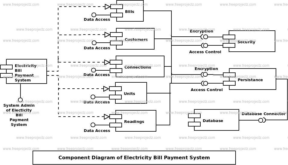
Electricity Bill Payment System Component Diagram
This is a Component diagram of Electricity Bill Payment System which shows components, provided and required interfaces, ports, and relationships between the Consuptions, Connections, Readings, Bills and Units. This type of diagrams is used in Component-Based Development (CBD) to describe systems with Service-Oriented Architecture (SOA). Electricity Bill Payment System UML component diagram, describes the organization and wiring of the physical components in a system.
Components of UML Component Diagram of Electricity Bill Payment System:
- Consuptions Component
- Connections Component
- Readings Component
- Bills Component
- Units Component
Featues of Electricity Bill Payment System Component Diagram:
- You can show the models the components of Electricity Bill Payment System.
- Model the database schema of Electricity Bill Payment System
- Model the executables of an application of Electricity Bill Payment System
- Model the system's source code of Electricity Bill Payment System
- Posted By: freeproject
- Comments: 0
Electricity Billing System Dataflow Diagram
Electricity Billing System Data flow diagram is often used as a preliminary step to create an overview of the Electricity without going into great detail, which can later be elaborated.it normally consists of overall application dataflow and processes of the Electricity process. It contains all of the userflow and their entities such all the flow of Electric, Bills, Payment, Connections, Customer, Paid Record, Unpaid Record. All of the below diagrams has been used for the visualization of data processing and structured design of the Electricity process and working flow.
Zero Level Data flow Diagram(0 Level DFD) of Electricity Billing System :
This is the Zero Level DFD of Electricity Billing System, where we have eloborated the high level process of Electricity. It’s a basic overview of the whole Electricity Billing System or process being analyzed or modeled. It’s designed to be an at-a-glance view of Customer,Paid Record and Unpaid Record showing the system as a single high-level process, with its relationship to external entities of Electric,Bills and Payment. It should be easily understood by a wide audience, including Electric,Payment and Customer In zero leve DFD of Electricity Billing System, we have described the high level flow of the Electricity system.High Level Entities and proccess flow of Electricity Billing System:
- Managing all the Electric
- Managing all the Bills
- Managing all the Payment
- Managing all the Connections
- Managing all the Customer
- Managing all the Paid Record
- Managing all the Unpaid Record

First Level Data flow Diagram(1st Level DFD) of Electricity Billing System :
First Level DFD (1st Level) of Electricity Billing System shows how the system is divided into sub-systems (processes), each of which deals with one or more of the data flows to or from an external agent, and which together provide all of the functionality of the Electricity Billing System system as a whole. It also identifies internal data stores of Unpaid Record, Paid Record, Customer, Connections, Payment that must be present in order for the Electricity system to do its job, and shows the flow of data between the various parts of Electric, Payment, Paid Record, Unpaid Record, Customer of the system. DFD Level 1 provides a more detailed breakout of pieces of the 1st level DFD. You will highlight the main functionalities of Electricity.Main entities and output of First Level DFD (1st Level DFD):
- Processing Electric records and generate report of all Electric
- Processing Bills records and generate report of all Bills
- Processing Payment records and generate report of all Payment
- Processing Connections records and generate report of all Connections
- Processing Customer records and generate report of all Customer
- Processing Paid Record records and generate report of all Paid Record
- Processing Unpaid Record records and generate report of all Unpaid Record

Second Level Data flow Diagram(2nd Level DFD) of Electricity Billing System :
DFD Level 2 then goes one step deeper into parts of Level 1 of Electricity. It may require more functionalities of Electricity to reach the necessary level of detail about the Electricity functioning. First Level DFD (1st Level) of Electricity Billing System shows how the system is divided into sub-systems (processes). The 2nd Level DFD contains more details of Unpaid Record, Paid Record, Customer, Connections, Payment, Bills, Electric.Low level functionalities of Electricity Billing System
- Admin logins to the system and manage all the functionalities of Electricity Billing System
- Admin can add, edit, delete and view the records of Electric, Payment, Customer, Unpaid Record
- Admin can manage all the details of Bills, Connections, Paid Record
- Admin can also generate reports of Electric, Bills, Payment, Connections, Customer, Paid Record
- Admin can search the details of Bills, Customer, Paid Record
- Admin can apply different level of filters on report of Electric, Connections, Customer
- Admin can tracks the detailed information of Bills, Payment, Connections, , Customer

- Posted By: freeproject
- Comments: 0
Electricity Bill Payment System ER Diagram
This ER (Entity Relationship) Diagram represents the model of Electricity Bill Payment System Entity. The entity-relationship diagram of Electricity Bill Payment System shows all the visual instrument of database tables and the relations between Customers, Units, Bills, Consuptions etc. It used structure data and to define the relationships between structured data groups of Electricity Bill Payment System functionalities. The main entities of the Electricity Bill Payment System are Bills, Customers, Connections, Units, Readings and Consuptions.
Electricity Bill Payment System entities and their attributes :
- Bills Entity : Attributes of Bills are bill_id, bill_customer_id, bill_number, bill_type, bill_receipt, bill_description
- Customers Entity : Attributes of Customers are customer_id, customer_name, customer_mobile, customer_email, customer_username, customer_password, customer_address
- Connections Entity : Attributes of Connections are connection_id, connection_name, connection_type, connection_description
- Units Entity : Attributes of Units are unit_id, unit_name, unit_type, unit_description
- Readings Entity : Attributes of Readings are reading_id, reading_name, reading_type, reading_description
- Consuptions Entity : Attributes of Consuptions are consuption_id, consuption_name, consuption_type, consuption_description
Description of Electricity Bill Payment System Database :
- The details of Bills is store into the Bills tables respective with all tables
- Each entity (Consuptions, Connections, Readings, Customers, Bills) contains primary key and unique keys.
- The entity Connections, Readings has binded with Bills, Customers entities with foreign key
- There is one-to-one and one-to-many relationships available between Readings, Units, Consuptions, Bills
- All the entities Bills, Readings, Connections, Consuptions are normalized and reduce duplicacy of records
- We have implemented indexing on each tables of Electricity Bill Payment System tables for fast query execution.

- Posted By: freeproject
- Comments: 0
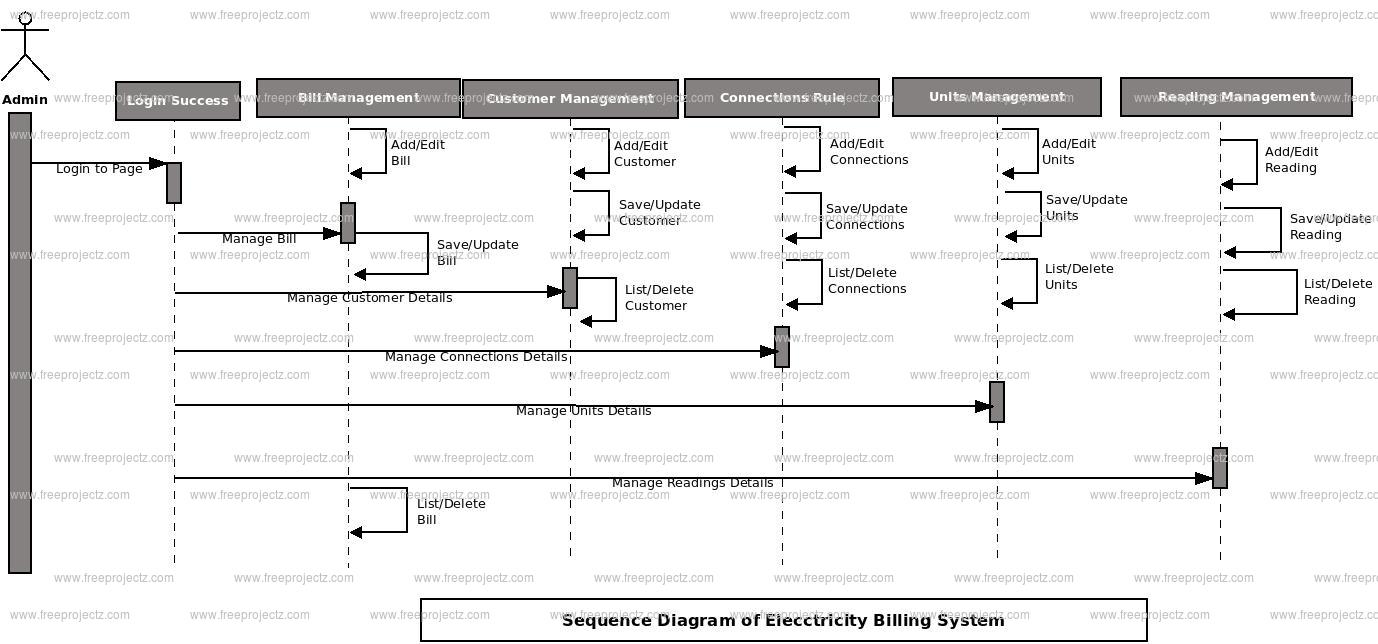
Electricity Bill Payment System Sequence Diagram
This is the UML sequence diagram of Electricity Bill Payment System which shows the interaction between the objects of Customers, Readings, Consuptions, Units, Bills. The instance of class objects involved in this UML Sequence Diagram of Electricity Bill Payment System are as follows:
- Customers Object
- Readings Object
- Consuptions Object
- Units Object
- Bills Object
Login Sequence Diagram of Electricity Bill Payment System:
This is the Login Sequence Diagram of Electricity Bill Payment System, where admin will be able to login in their account using their credentials. After login user can manage all the operations on Consuptions, Customers, Readings, Bills, Units. All the pages such as Readings, Bills, Units are secure and user can access these page after login. The diagram below helps demonstrate how the login page works in a Electricity Bill Payment System. The various objects in the Bills, Consuptions, Customers, Readings, and Units page—interact over the course of the sequence, and user will not be able to access this page without verifying their identity.
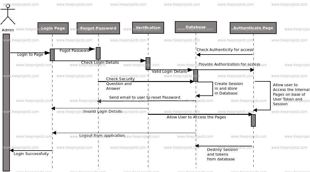
This is the UML sequence diagram of Electricity Bill Payment System which shows the interaction between the objects of Customers, Readings, Consuptions, Units, Bills. The instance of class objects involved in this UML Sequence Diagram of Electricity Bill Payment System are as follows:
- Customers Object
- Readings Object
- Consuptions Object
- Units Object
- Bills Object
- Posted By: freeproject
- Comments: 0
Electricity Bill Payment System Use Case Diagram
This Use Case Diagram is a graphic depiction of the interactions among the elements of Electricity Bill Payment System. It represents the methodology used in system analysis to identify, clarify, and organize system requirements of Electricity Bill Payment System. The main actors of Electricity Bill Payment System in this Use Case Diagram are: Super Admin, System User, Customer, Cashier, who perform the different type of use cases such as Manage Bills, Manage Customers, Manage Connections, Manage Units, Manage Readings, Manage Consuptions, Manage Users and Full Electricity Bill Payment System Operations. Major elements of the UML use case diagram of Electricity Bill Payment System are shown on the picture below.
The relationships between and among the actors and the use cases of Electricity Bill Payment System:
- Super Admin Entity : Use cases of Super Admin are Manage Bills, Manage Customers, Manage Connections, Manage Units, Manage Readings, Manage Consuptions, Manage Users and Full Electricity Bill Payment System Operations
- System User Entity : Use cases of System User are Manage Bills, Manage Customers, Manage Connections, Manage Units, Manage Readings, Manage Consuptions
- Customer Entity : Use cases of Customer are Check Bills, Check Bill Summary, Make Payment, Check Payment History
- Cashier Entity : Use cases of Cashier are Collect Payments, Create Bills, Search Customers, Manage Payments
Use Case Diagram of Electricity Bill Payment System :