- Posted By: freeproject
- Comments: 0
- Posted By: freeproject
- Comments: 0
Petrol Pump Management System Activity Diagram
This is the Activity UML diagram of Petrol Pump Management System which shows the flows between the activity of Inventory, Fule, Tankers, Stocks, Sales. The main activity involved in this UML Activity Diagram of Petrol Pump Management System are as follows:
- Inventory Activity
- Fule Activity
- Tankers Activity
- Stocks Activity
- Sales Activity
Features of the Activity UML diagram of Petrol Pump Management System
- Admin User can search Inventory, view description of a selected Inventory, add Inventory, update Inventory and delete Inventory.
- Its shows the activity flow of editing, adding and updating of Fule
- User will be able to search and generate report of Tankers, Stocks, Sales
- All objects such as ( Inventory, Fule, Sales) are interlinked
- Its shows the full description and flow of Inventory, Stocks, Sales, Tankers, Fule

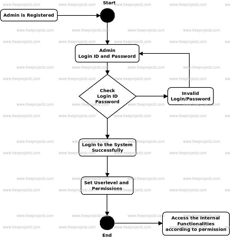
Login Activity Diagram of Petrol Pump Management System:
This is the Login Activity Diagram of Petrol Pump Management System, which shows the flows of Login Activity, where admin will be able to login using their username and password. After login user can manage all the operations on Tankers, Inventory, Fule, Sales, Stocks. All the pages such as Fule, Sales, Stocks are secure and user can access these page after login. The diagram below helps demonstrate how the login page works in a Petrol Pump Management System. The various objects in the Sales, Tankers, Inventory, Fule, and Stocks page—interact over the course of the Activity, and user will not be able to access this page without verifying their identity.
- Posted By: freeproject
- Comments: 0
Petrol Pump Management System Class Diagram
Petrol Pump Management System Class Diagram describes the structure of a Petrol Pump Management System classes, their attributes, operations (or methods), and the relationships among objects. The main classes of the Petrol Pump Management System are Fule, Sales, Stocks, Tankers, Meter Readings, Inventory.
Classes of Petrol Pump Management System Class Diagram:
- Fule Class : Manage all the operations of Fule
- Sales Class : Manage all the operations of Sales
- Stocks Class : Manage all the operations of Stocks
- Tankers Class : Manage all the operations of Tankers
- Meter Readings Class : Manage all the operations of Meter Readings
- Inventory Class : Manage all the operations of Inventory
Classes and their attributes of Petrol Pump Management System Class Diagram:
- Fule Attributes : fule_id, fule_name, fule_type, fule_description
- Sales Attributes : sales_id, sales_customer_id, sales_amount, sales_type, sales_description
- Stocks Attributes : stock_id, stock_items, stock_number, stock_type, stock_description
- Tankers Attributes : tanker_id, tanker_fuel_id, tanker_name, tanker_type, tanker_description
- Meter Readings Attributes : reading_id, reading_name, reading_type, reading_description
- Inventory Attributes : inventory_id, inventory_items, inventory_number, inventory_type, inventory_description
Classes and their methods of Petrol Pump Management System Class Diagram:
- Fule Methods : addFule(), editFule(), deleteFule(), updateFule(), saveFule(), searchFule()
- Sales Methods : addSales(), editSales(), deleteSales(), updateSales(), saveSales(), searchSales()
- Stocks Methods : addStocks(), editStocks(), deleteStocks(), updateStocks(), saveStocks(), searchStocks()
- Tankers Methods : addTankers(), editTankers(), deleteTankers(), updateTankers(), saveTankers(), searchTankers()
- Meter Readings Methods : addMeter Readings(), editMeter Readings(), deleteMeter Readings(), updateMeter Readings(), saveMeter Readings(), searchMeter Readings()
- Inventory Methods : addInventory(), editInventory(), deleteInventory(), updateInventory(), saveInventory(), searchInventory()
Class Diagram of Petrol Pump Management System :

- Posted By: freeproject
- Comments: 0
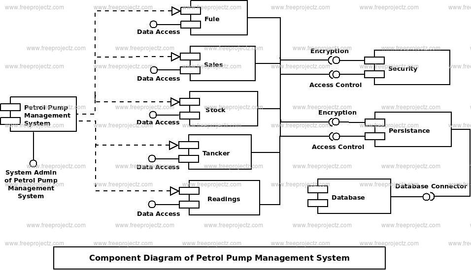
Petrol Pump Management System Component Diagram
This is a Component diagram of Petrol Pump Management System which shows components, provided and required interfaces, ports, and relationships between the Reading, Sales, Inventory, Tankers and Fule. This type of diagrams is used in Component-Based Development (CBD) to describe systems with Service-Oriented Architecture (SOA). Petrol Pump Management System UML component diagram, describes the organization and wiring of the physical components in a system.
Components of UML Component Diagram of Petrol Pump Management System:
- Reading Component
- Sales Component
- Inventory Component
- Tankers Component
- Fule Component
Featues of Petrol Pump Management System Component Diagram:
- You can show the models the components of Petrol Pump Management System.
- Model the database schema of Petrol Pump Management System
- Model the executables of an application of Petrol Pump Management System
- Model the system's source code of Petrol Pump Management System
- Posted By: freeproject
- Comments: 0
Petrol Pump Management System ER Diagram
This ER (Entity Relationship) Diagram represents the model of Petrol Pump Management System Entity. The entity-relationship diagram of Petrol Pump Management System shows all the visual instrument of database tables and the relations between Sales, Tankers, Fule, Inventory etc. It used structure data and to define the relationships between structured data groups of Petrol Pump Management System functionalities. The main entities of the Petrol Pump Management System are Fule, Sales, Stocks, Tankers, Meter Readings and Inventory.
Petrol Pump Management System entities and their attributes :
- Fule Entity : Attributes of Fule are fule_id, fule_name, fule_type, fule_description
- Sales Entity : Attributes of Sales are sales_id, sales_customer_id, sales_amount, sales_type, sales_description
- Stocks Entity : Attributes of Stocks are stock_id, stock_items, stock_number, stock_type, stock_description
- Tankers Entity : Attributes of Tankers are tanker_id, tanker_fuel_id, tanker_name, tanker_type, tanker_description
- Meter Readings Entity : Attributes of Meter Readings are reading_id, reading_name, reading_type, reading_description
- Inventory Entity : Attributes of Inventory are inventory_id, inventory_items, inventory_number, inventory_type, inventory_description
Description of Petrol Pump Management System Database :
- The details of Fule is store into the Fule tables respective with all tables
- Each entity ( Inventory, Stocks, Meter Readings, Sales, Fule) contains primary key and unique keys.
- The entity Stocks, Meter Readings has binded with Fule, Sales entities with foreign key
- There is one-to-one and one-to-many relationships available between Meter Readings, Tankers, Inventory, Fule
- All the entities Fule, Meter Readings, Stocks, Inventory are normalized and reduce duplicacy of records
- We have implemented indexing on each tables of Petrol Pump Management System tables for fast query execution.

- Posted By: freeproject
- Comments: 0
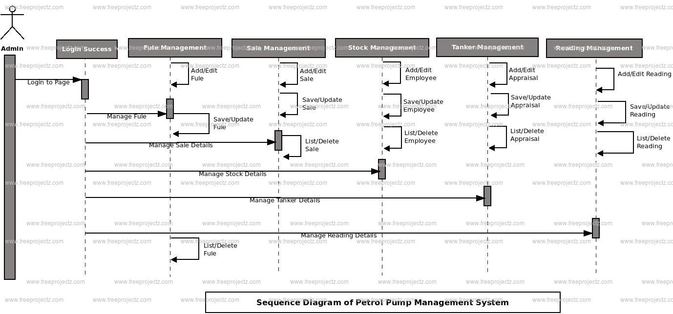
Petrol Pump Management System Sequence Diagram
This is the UML sequence diagram of Petrol Pump Management System which shows the interaction between the objects of Inventory, Reading, Sales, Fule, Tankers. The instance of class objects involved in this UML Sequence Diagram of Petrol Pump Management System are as follows:
- Inventory Object
- Reading Object
- Sales Object
- Fule Object
- Tankers Object
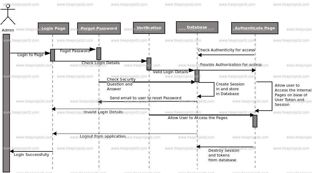
Login Sequence Diagram of Petrol Pump Management System:
This is the Login Sequence Diagram of Petrol Pump Management System, where admin will be able to login in their account using their credentials. After login user can manage all the operations on Sales, Inventory, Reading, Tankers, Fule. All the pages such as Reading, Tankers, Fule are secure and user can access these page after login. The diagram below helps demonstrate how the login page works in a Petrol Pump Management System. The various objects in the Tankers, Sales, Inventory, Reading, and Fule page—interact over the course of the sequence, and user will not be able to access this page without verifying their identity.
This is the UML sequence diagram of Petrol Pump Management System which shows the interaction between the objects of Inventory, Reading, Sales, Fule, Tankers. The instance of class objects involved in this UML Sequence Diagram of Petrol Pump Management System are as follows:
- Inventory Object
- Reading Object
- Sales Object
- Fule Object
- Tankers Object
- Posted By: freeproject
- Comments: 0
Petrol Pump Management System Use Case Diagram
This Use Case Diagram is a graphic depiction of the interactions among the elements of Petrol Pump Management System. It represents the methodology used in system analysis to identify, clarify, and organize system requirements of Petrol Pump Management System. The main actors of Petrol Pump Management System in this Use Case Diagram are: Super Admin, System User, Dealers, Anonymous Users, who perform the different type of use cases such as Manage Fule, Manage Sales, Manage Stocks, Manage Tankers, Manage Meter Readings, Manage Inventory, Manage Users and Full Petrol Pump Management System Operations. Major elements of the UML use case diagram of Petrol Pump Management System are shown on the picture below.
The relationships between and among the actors and the use cases of Petrol Pump Management System:
- Super Admin Entity : Use cases of Super Admin are Manage Fule, Manage Sales, Manage Stocks, Manage Tankers, Manage Meter Readings, Manage Inventory, Manage Users and Full Petrol Pump Management System Operations
- System User Entity : Use cases of System User are Manage Fule, Manage Sales, Manage Stocks, Manage Tankers, Manage Meter Readings, Manage Inventory
- Dealers Entity : Use cases of Dealers are View Stocks, Order of New Stocks, Create Invoices, Manage Tankers, Make Payments, View Inventories
- Anonymous Users Entity : Use cases of Anonymous Users are View Information, Fill Contact Us, Search Content
Use Case Diagram of Petrol Pump Management System :